Celenit L3
natural laminated insulation
boards for external walls
Celenit L3 and
Celenit L3AB/A2 (panels with A2 fire rating)
External Wall Insulation
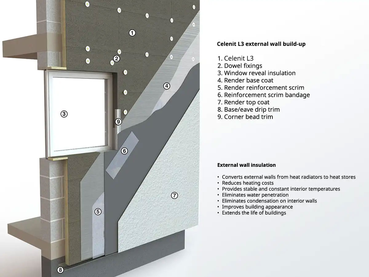
The purpose designed, Celenit L3 laminated insulation board forms the heart of an external wall insulation system that is simple to install. The boards, trims and sections are easy to cut and fasten and the application of render only requires the skill of a competent plasterer.
Originally designed for the external insulation of solid masonry walls Celenit L3 insulation boards can span up to 1000mm and so may also be applied to timber or steel frame walls.
Traditional lime renders and other render products may be applied on Celenit L3 boards but approval should be sought prior to application.
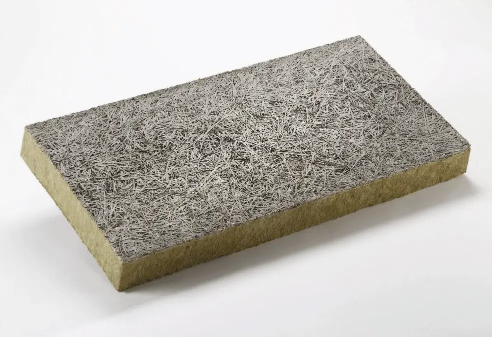
Board Sizes
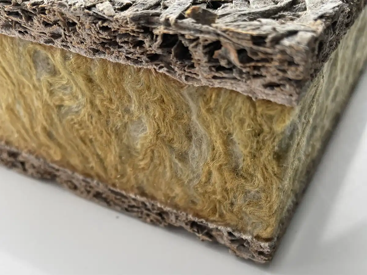
The Celenit L3 insulation board consists of non combustible rockwool core sandwiched between two layers of wood cement composite. It is available in the following sizes:
- 2000 × 600 × 50 mm
- 2000 × 600 × 75 mm
- 2000 × 600 × 100 mm
- 2000 × 600 × 125 mm
- 2000 × 600 × 150 mm
- 2000 × 600 × 175 mm
Click on image to view full size
Celenit L3 Advantages
- Resistant to impact and compression damage
- Tough, rigid, easily cut and fix insulation boards
- Secure mechanical fastening
- Can install over existing rendered walls
- Insulation boards can span over irregularities
- “Breathing” system allowing moisture diffusion
- Sound insulating and fire resistant
- Good render bonding board surface
- Well-proven, two-coat, through-colour render system
- User friendly system available direct for building contractors
- Full technical support and site instruction available
- Also available with A2 fire rating (Celenit L3AB/A2)
Energy conservation and environmental protection through effective thermal insulation
| Wall Construction | U-Value |
|---|---|
| Solid 220mm (9”) brick wall | 2.08 W/m2K |
| + 50mm Celenit L3 and render | 0.59 W/m2K |
| + 75mm Celenit L3 and render | 0.43 W/m2K |
| + 100mm Celenit L3 and render | 0.33 W/m2K |
| + 125mm Celenit L3 and render | 0.28 W/m2K |
External Wall System
Click on image to view full size
Click on image to view full size
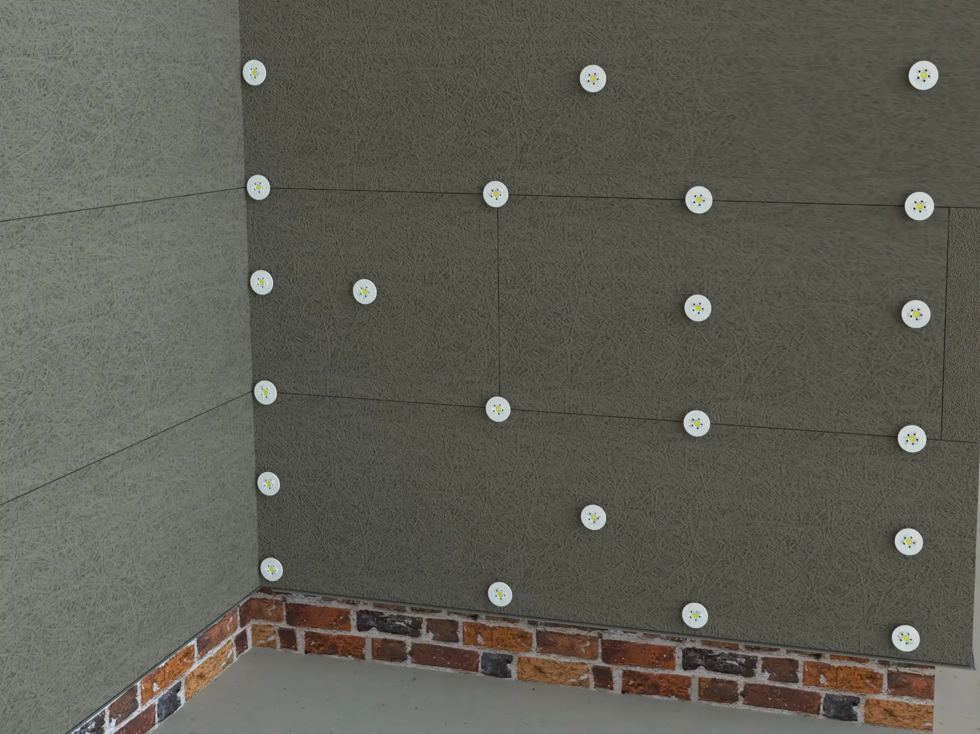
Dowel layout at base wall
Click on image to view full size
External wall corner
Click on image to view full size
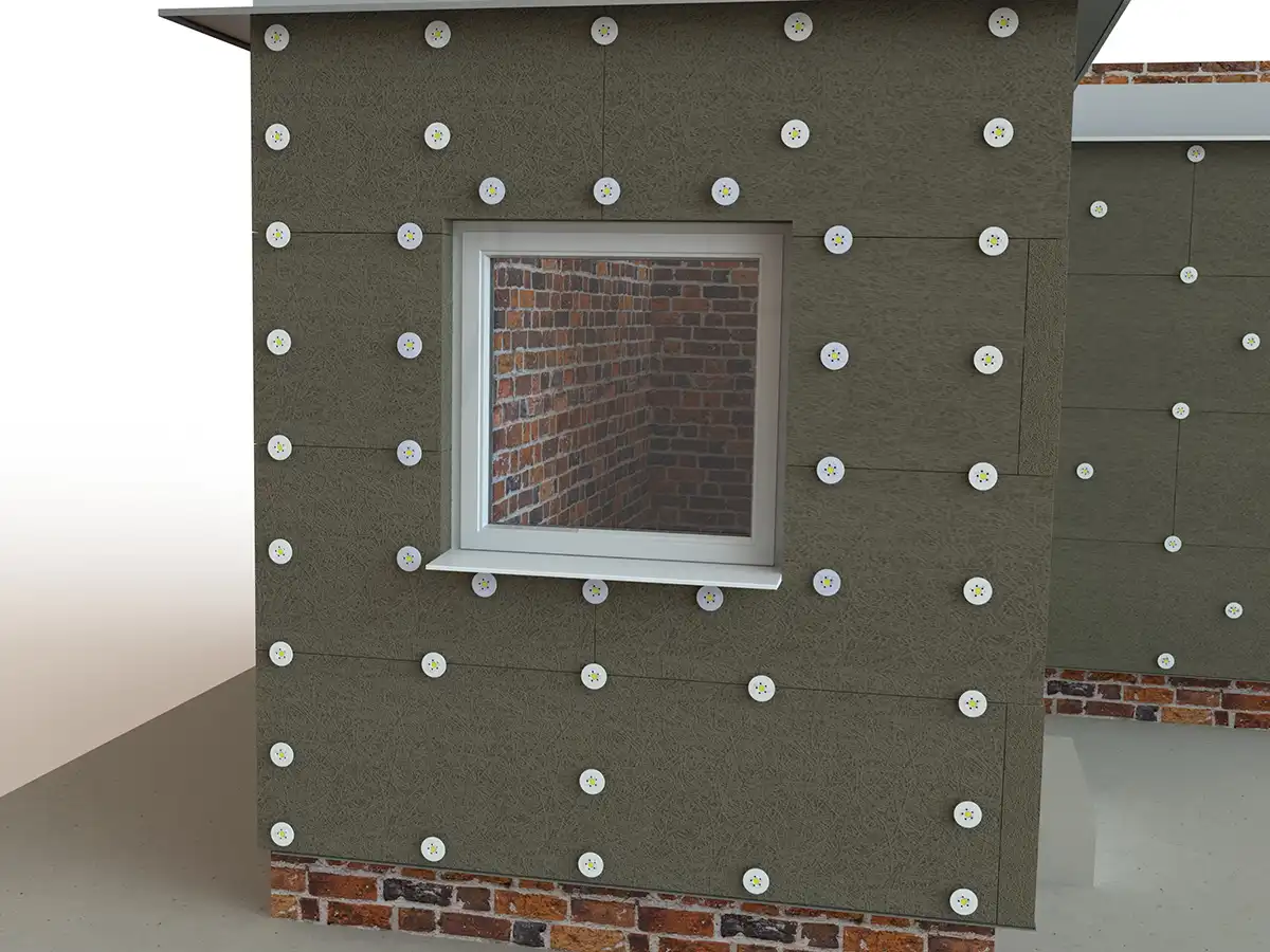
Wall opening (window)
Click on image to view full size
Installation Guide
Click on images to view full size
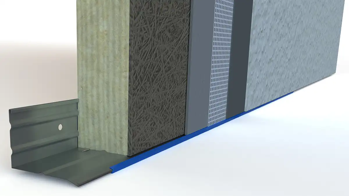
Base Profile
Base / eave drip sections are aligned horizontally and fixed with suitably plated screws and plugs to the wall. The minimum distance from the edge of the base profile to the ground surface should not be less than 200mm and the base profile should not be positioned below any damp course.
The base profile section seals off the bottom edges of the Celenit L3 board and also forms a render drip edge.
Celenit L3 Insulation Boards
The first course of Celenit L3 boards is placed on the base profile and each board is initially fixed in the centre with a dowel. The boards are placed horizontally, in broken bond, butted tightly together and fixed with dowels at the board butt joints. Board end joints are alternated at building corners. Any narrow cut board pieces should additionally be fixed with P010 Adhesive.
Prior to installation Celenit L3 boards should be stored dry and flat. Boards are cut with hand or circular saw. Small pieces are best cut with the board laid flat and both pieces installed immediately to minimise wastage.
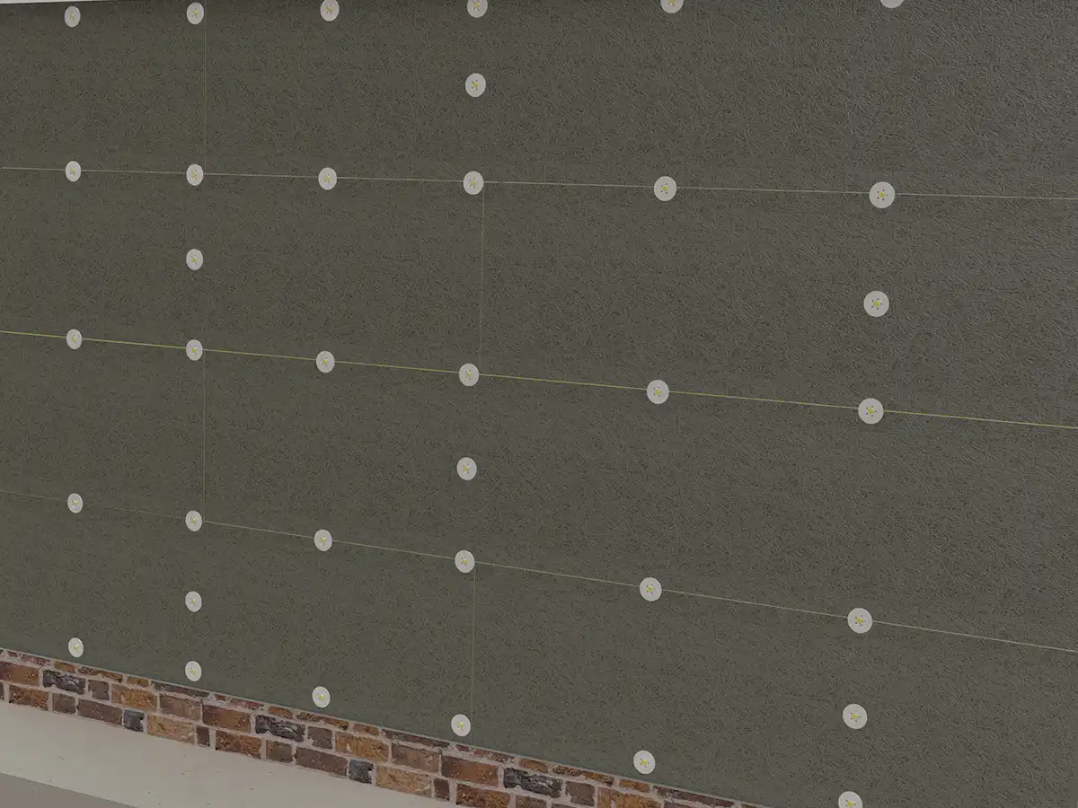
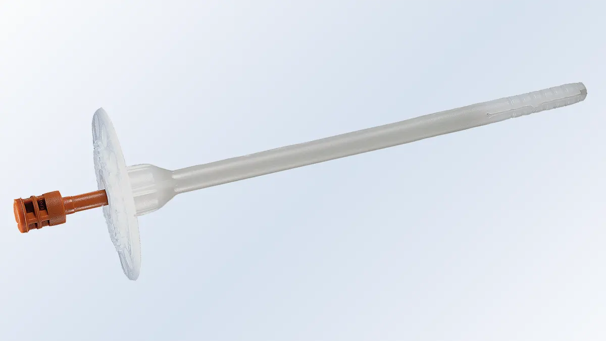
Dowels
Dowels are placed at board joints at maximum 600mm centres. Extra dowels are used at corners, along the base profile and around openings (see diagrams). The number and length of dowels will depend upon the type of masonry, building height, wind loadings and render weight. It is the responsibility of the installer to ensure the correct number and length of dowels are used and, if necessary, to carry out drilling and dowel pull-out tests.
| Dowels Required | m² |
|---|---|
| Minimum | 6 no./ m² |
| Average | 8 no./ m² |
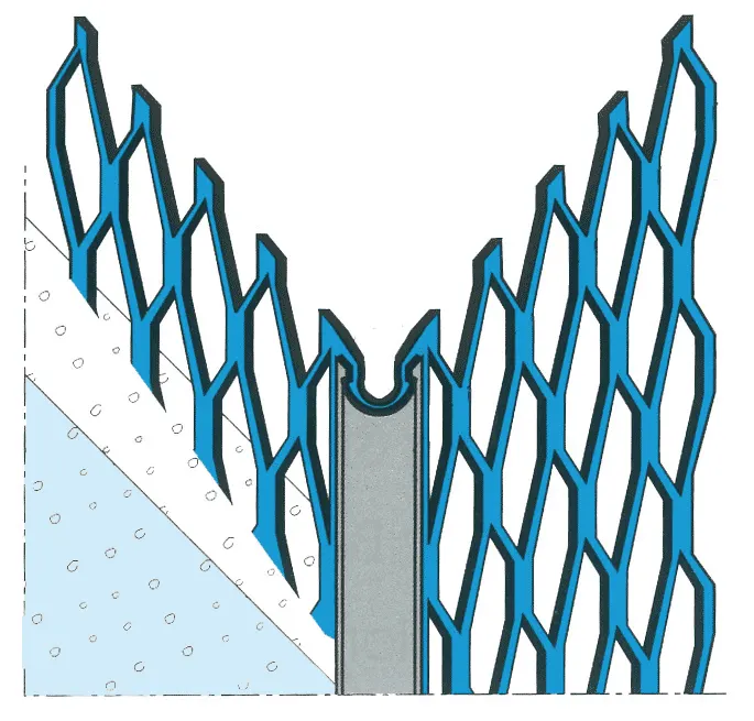
Corner Bead
Corner beads ensure the render is true and are cemented to the Celenit L3 board surface with P010 Adhesive at external corners of walls, doors and window reveals and aligned and positioned to suit the render thickness. The glass fibre render reinforcement mesh is taken up tight to the corner trim.
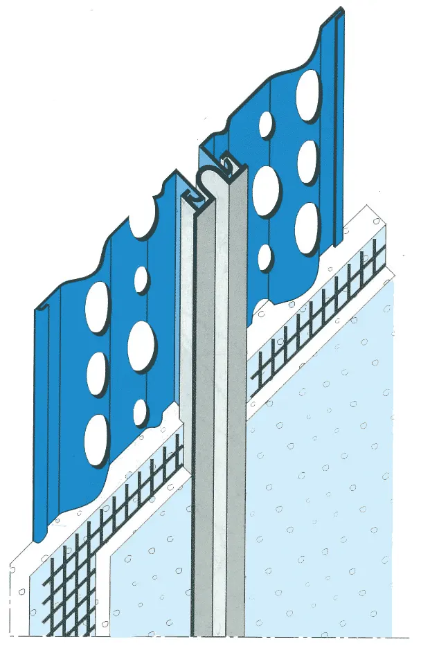
Expansion Joint/Movement Joint Bead
Large uninterrupted areas of render should be divided at intervals of approximately 5 metres with movement/expansion joint beads and these also should be installed at connections to existing structures and structural expansion joints.
Where expansion/movement joint beads are fitted the Celenit L3 boards should be cut through to the substructure. Expansion/movement joint beads are cemented to the Celenit L3 board surface using P010 Adhesive.
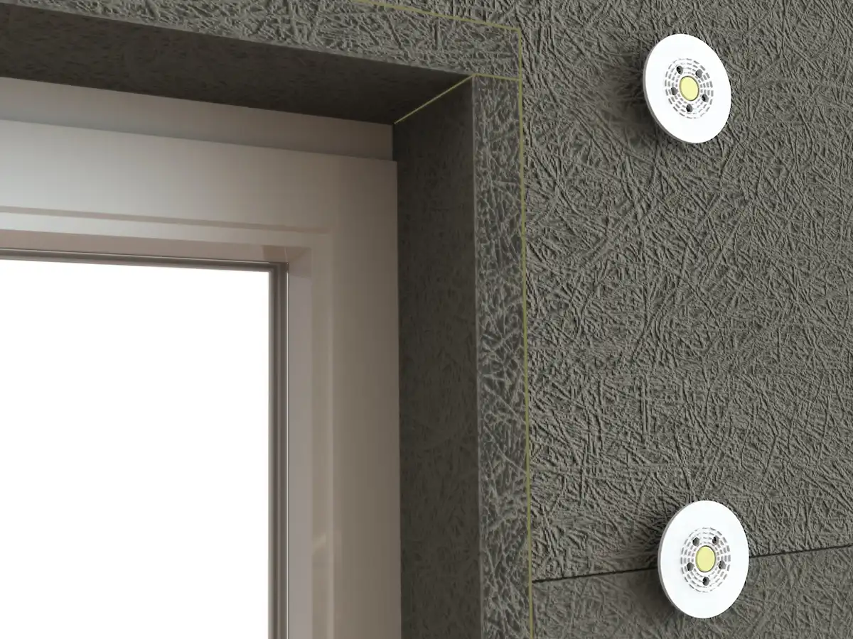
Reveals
Reveal insulation pieces are cut from Celenit L3 and Savolit board and stuck around door and window reveals with P010 Adhesive and additionally fixed with dowels at 500mm centres.
Reveal pieces prevent heat transfer and so with old buildings it is important to remove any existing render to gain space for the thermal insulation. At the window jamb the render must be cut with the trowel edge and the joint filled with suitable flexible filler.
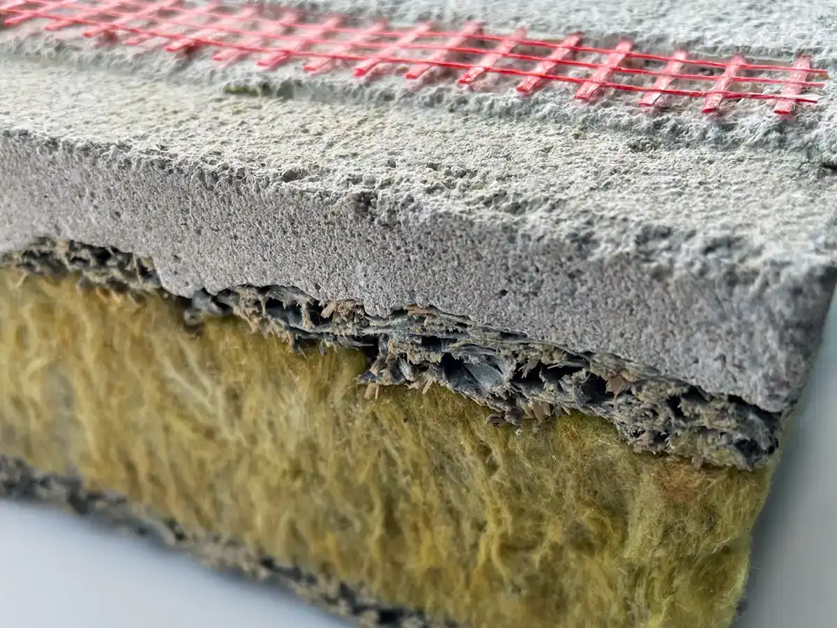
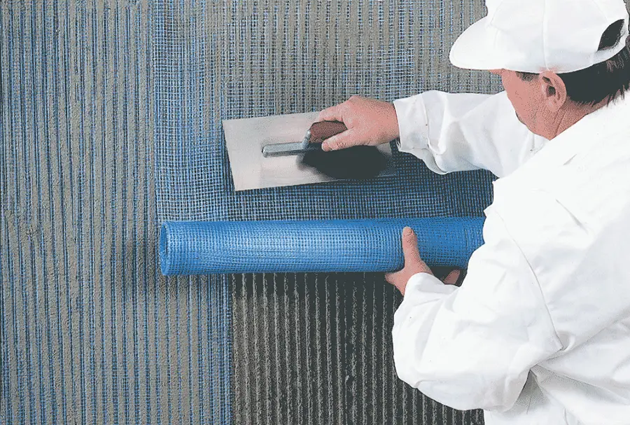
Render Reinforcement Mesh
It is recommended that render reinforcement mesh is incorporated within renders applied to Celenit L3 and Savolit boards to absorb stresses.
The mesh edges must be overlapped at least 100mm (coverage approx. 1.2m² for each square metre of wall surface). In addition, strips of mesh 600 x 200mm, should be placed diagonally as reinforcement to absorb stresses at corners of doors and windows.
Technical Data
| Property | Units | Data | ||||||
|---|---|---|---|---|---|---|---|---|
| Standard | EN 13168 | |||||||
| Length x Width | mm | 2000 x 600 | ||||||
| Thickness | mm | 35 | 50 | 75 | 100 | 125 | 150 | |
| Layers structure | mm | 5/25/5 | 5/40/5 | 5/65/5 | 5/90/5 | 5/115/5 | 5/140/5 | |
| Weight | kg/m² | 10.8 | 12.3 | 15.4 | 18.7 | 22.1 | 25.5 | |
| Declared thermal conductivity λD | W/mK | WW: 0.071 – MW: 0.039 | ||||||
| Declared thermal resistance RD | m²K/W | 0.75 | 1.15 | 1.80 | 2.45 | 3.05 | 3.70 | |
| Thermal resistance R | m²K/W | 0.75 | 1.17 | 1.81 | 2.45 | 3.09 | 3.70 | |
| Compressive strength σm | kPa | ≥ 50 | ||||||
| Tensile strength perpendicular to faces σmt |
kPa | ≥ 15 | ≥ 20 | |||||
| Water vapour transmission µ | WW 5 – MW 1 | |||||||
| Reaction to fire | Euroclass B-s1, d0 | |||||||